|
Structure
The
aluminium cylinder block is fitted with cast iron
cylinder liners. Four
cast iron crankshaft bearings are fitted to the
aluminium crankcase at
the casting stage. Major design changes to the
aluminium cylinder head
include enhanced combustion chambers and inlet ducts,
which increase
power output and torque, while lowering exhaust
emissions.
The
new inlet manifold, in composite material, comprises
six ducts of equal
length. These are mounted on an aluminium distributor
attached to the
cylinder heads in the centre of the V. The distributor
comprises 12
ducts, each with a variable cross-sectional area, and
each feeding a
single valve.
This layout
optimises the flow into the cylinders.
The
position of the electronic throttle is precisely
controlled by the
computer in response to a large number of parameters,
including
accelerator pedal position, coolant temperature and
incoming air
temperature.
Rotating
assembly
Improved
fuel consumption and lower vibration have been
achieved through
extensive design studies seeking to reduce friction
and to make parts
lighter.
The
forged steel crankshaft includes five precision-ground
case-hardened
bearing sections. The bearing grooves and journals are
rolled in
sections. In contrast to traditional rolling
techniques, this process
hardens the metal without distorting the crankshaft,
thereby improving
stress resistance.
The forged steel
connecting rods feature integral oil channels for
cylinder lubrication and cooling.
The
pistons are 40 g lighter than those in the previous
version. The flat
piston tops are raised slightly in the centre, with
rebates to provide
valve clearance.
A
flexible engine flywheel reduces engine vibration at
high speeds. The
flywheel consists of a cast friction ring on the
clutch side and a
sheet metal damping mechanism on the engine side.
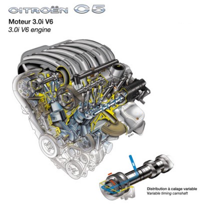
Valve gear
The four
camshafts act directly on hydraulic tappets that
automatically take up any play in the system.
A phase shifter,
or variable-timing camshaft, adjusts the timing of the
valve gear for optimum flow into the cylinder.
For
example, during acceleration at low engine speeds,
valve lead and lag
take place earlier.The inlet camshafts are moved
between two possible
positions by means of a double helical ramp controlled
by the oil
pressure. The engine computer controls the oil intake
through an
electrovalve, in accordance with engine speed, engine
load and oil
temperature. The camshaft position is monitored by an
angular position
sensor.
Injection and
ignition
The
engine is controlled by a Bosch ME 7.4 engine control
system driving
the sequential injection system and coil-per-plug
ignition. The new
multi-jet injectors are fed from two rails with no
fuel return. The
fuel circuit includes a surge damper to eliminate
noise and variations
in pressure.
Exhaust and
emission control
A pre-catalyst
is mounted at the outlet of each exhaust manifold,
with oxygen sensors fitted at the inlet and
outlet.
The
sensors analyse the oxygen content of the exhaust gas
and transmit the
information to the engine control system, which then
adjusts the fuel /
air ratio accordingly. The main catalytic converter
completes the
pollution control system, ensuring emission levels
compliant with the
Euro 4 standard.
|