|
||||||||||||||||||||||
|
||||||||||||||||||||||
 |
Citroën hydraulic systemClick on the
Hydropneumatique image to return here
|
|||||
| 1977
Hydraulique
haute pression brochure |
||||||
| Anti-roll
suspension
- in 1955 and other developments |
Hydropneumatically sprung 2CV
prototype |
|||||
| Traction
Avant
15CV H and DS19 |
GS |
|||||
| SM |
GSA |
|||||
| CX |
BX |
|||||
| XM |
Citroën UK leaflet |
|||||
| 1989
Hydractive brochure |
Hydractive 3 | |||||
| Xantia |
About the hydropneumatic system by Julian Marsh | |||||
| Hydropneumatics article | 40 jaar hydropneumatische
vering van DS tot Activa |
|||||
| 40 ans de suspension
hydropneumatique |
DS clutchless gearchange |
|||||
| Practical Classics hydropneumatic photo shoot (the bubble bursts) | English booklet that explains the workings of the hydraulic systems | |||||
| French booklet that explains the workings of the hydraulic systems | ||||||
| Dutch D series range hydraulics | French
D series range hydraulics |
|||||
|
|
||||||
|
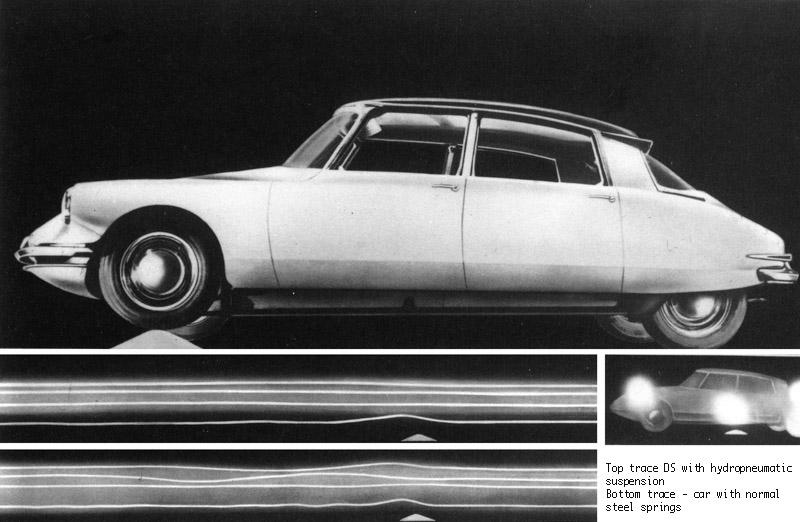
Citroën's hydropneumatic* suspension, despite a reputation for complexity, complication and unreliability is actually very simple in operation and very reliable and furthermore, offers an unrivalled level of comfort coupled with excellent handling and grip. *The system is also referred to as 'oléopneumatique' in early literature. |
 |
|||||
|
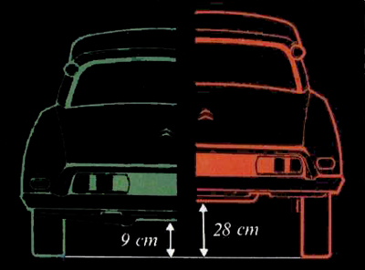
The system takes advantage of the fact that you can compress a gas but cannot compress a fluid. Thus gas acts as the springing medium while the hydraulic fluid does all the clever things such as providing damping and levelling. Unlike the hydrolastic system fitted to certain BMC and BLMC cars, the Citroën system relies on an engine-driven pump to pressurise the hydraulic system and it is this power source which enables self-levelling, variable ride height, assisted jacking and zero roll (in the Activa Xantia) and also allows for fully powered braking systems and power steering too. The system provides a soft, comfortable, yet well-controlled ride. The nitrogen springing medium is approximately six times more flexible than a conventional steel system, so self-leveling is incorporated to allow the vehicle to cope with the extraordinary suppleness provided. In the early fifties, France was noted for particularly poor road quality and therefore the only way to maintain a relatively high speed in a vehicle was if it could easily absorb road irregularities. It was this need that also drove the development of the 2CV's interconnected suspension system. |
||||||
 |
||||||
|
In the DS, the high pressure hydraulic system also operated the clutch and gear change. With the introduction of the XM came electronic control of the suspension system - called Hydractive and a refined version of this system was fitted to high specification Xantias and to later XMs. The Hydractive system allowed for variable damping and automatic switching between soft and firm modes which allowed an unparalleled combination of ride comfort and good handling. Hydropneumatic suspension was first shown in 1954 when it was fitted to the rear of the 15CV H Traction Avant . This was a foretaste of the system that was fitted to the astonishing DS 19 of 1955. Variants of the suspension have been fitted subsequently to the GS of 1970, the SM of the same year, the CX , the BX , the XM, the Xantia most C5s and the C6. Other cars fitted with the system were the M 35 Wankel-engined prototype, the GZ Birotor , some variants of the H van and various Rolls Royce and Mercedes-Benz cars where it was used under licence. For an excellent technical guide in Adobe Acrobat format covering all Citroën's hydraulic systems, click here and follow the link to Technical Guide.
|
||||||
 |
||||||
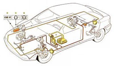
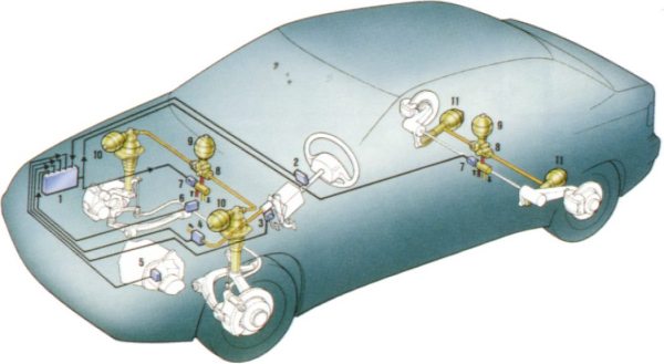
| 1. Computer 2. Steering wheel movement and speed of movement sensor 3. Accelerator sensor - reads accelerator movement and rate of movement 4. Brake sensor 5. Speed sensor 6. Body movement sensor 7. Electrovalve 8. Stiffness regulator 9. Extra sphere 10. Front suspension sphere 11. Rear suspension sphere |
Above the Hydractive 2 system fitted to high specification variants of the Xantia and XM. The system switches from "soft" to "firm" modes according to a number of parameters programmed into the on board computer. Sensors provide the necessary input to the computer to determine which mode is appropriate. A central sphere on each axle is switched in and out of circuit to alter the amount of suspension travel and damping. |
|||||
|
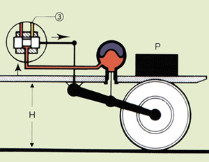
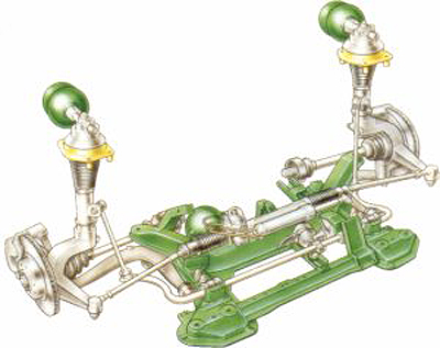
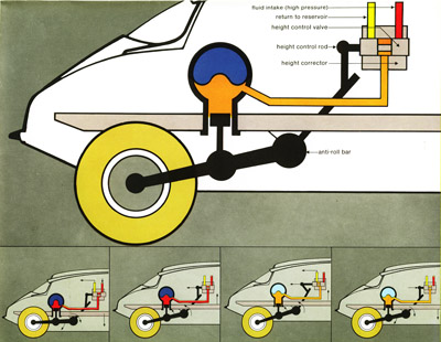
Below left the Xantia front suspension comprises MacPherson type struts with the Hydropneumatic suspension spheres mounted on top. Each sphere contains a diaphragm behind which a quantity of nitrogen is trapped. A height corrector is attached to the anti roll bar and when a load is placed in the car, the car body sinks. This movement is registered by the height corrector which opens a valve to admit hydraulic fluid under pressure to "lengthen" the hydraulic strut and thereby re-establish the correct ride height. A control inside the car allows the ride height to be varied by the driver thereby aiding wheel changes. |
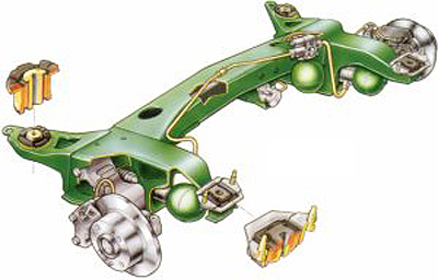
The SC-CAR or Activa system builds on Hydractive 2 by incorporating hydraulic jacks to counter body roll. Hydractive 2 is also fitted to most XM models. Below right the rear suspension of the Xantia comprises trailing arms connected to an anti roll bar with height corrector attached. The rear spheres lie flat which permits an unobstructed boot floor with no suspension unit intrusions. |
|||||
 |
 |
|||||
|
The hydraulic system acquired a reputation for unreliability when it was prematurely released on the DS. There were problems with seals and the fluid originally used was intensely hygroscopic (it absorbed water) which caused oxydisation and early DS drivers frequently discovered their pride and joy resting on its haunches in a pool of fluid. The introduction of LHS improved matters but it was not until a mineral oil LHM or Liquide Hydraulique Minéral was introduced in the mid sixties that the system became thoroughly reliable. In the DS, the hydraulic system provided power for the clutch, gearchange and steering. Additional uses of this system included the fully powered self centring steering system (DIRAVI or Varipower) fitted to the SM and CX, levelling of the headlamps fitted to the SM and a number of design studies were undertaken to investigate hydraulic operation of windscreen wipers, an air dam brake and even the opening and closing of windows. Prior to the advent of cheap electronics, a totally hydraulic anti lock braking system had been built, together with zero roll suspension. Electronics provided a cheap, low weight solution for active suspension and anti lock brakes. |
||||||
 |
||||||
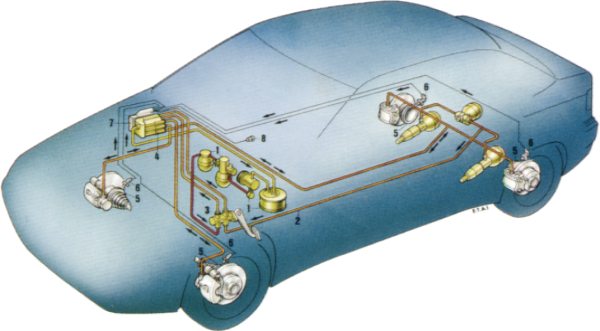
| 1. Front brakes accumulator 2. Front to rear brake line 3. Brake servo with front to rear compensator 4. Hydraulic distribution unit 5. Cogged wheel 6. Brake rotation sensor 7. Computer 8. Dashboard warning light |
Anti dive suspension is incorporated The rear brakes take their fluid from the rear suspension which pulls the tail down under heavy braking. On all hydraulic Citroëns (with the exception of some early ID 19s), the balance between front to rear braking effort is modified by the respective loads placed on the front and rear suspension. |
|||||
 |
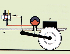
1.
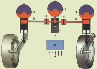
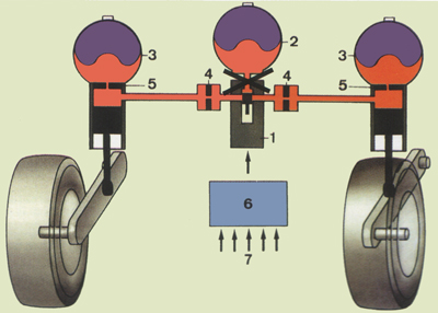
Electromagnetic valve 2. Stiffness regulator 3. Additional spheres 4. Front spheres 5. Rear spheres 6. Additional dampers 7. Dampers 8. Central computer 9. Sensors Top left -
suspension in "soft" state; the solenoid valve (1) is
energised, the slide valve opens allowing hydraulic fluid to flow
between the between the suspension cylinders and the
spheres (4 and 3) via the dampers (6). All six
spheres are in use. Bottom left - suspension is in "firm" mode; the solenoid valve (1) is not energised, the slide valve takes up a position which blocks the movement of hydraulic fluid between the two main spheres (4) on each axle and isolates the additional spheres (3) from them both. |
|||||
 |
||||||
 |
 |
|||||
SUSPENSION IN SOFT MODE
|
SUSPENSION IN FIRM
MODE
|
|||||
The C5 features a decentralised system employing separate systems for power steering and braking while future developments may feature a pump for each road wheel and a totally active system (the Activa is, in truth, reactive, albeit its reactions are so quick as to almost deserve the appellation) which reads the road surface ahead of the car and provides precisely the correct amount of suspension travel. |
||||||
 |
 |
|||||
|
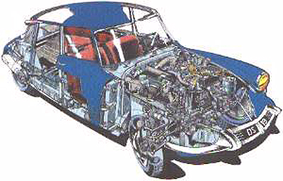
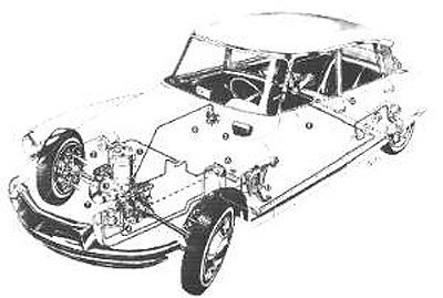
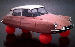
Above a schematic of the DS showing the suspension system Below a publicity shot for the DS showing the interaction between hydraulics, represented by water and air represented by the ballons. |
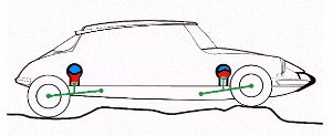
Above a schematic of the DS showing the braking system Below the suspension system showing the spheres with the nitrogen represented in blue and the hydraulic fluid in red |
|||||
 |
 |
|||||
 |
 |
|||||
 |
||||||
|
||||||
 |
||||||
|
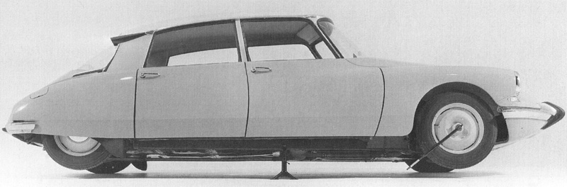
Another advantage of the variable ride height was the ability to dispense with a conventional jack. To jack the car up, all that was required was to place it in the highest suspension position, place a simple stand under the car and then select the lowest suspension position. The two wheels on the side of the car under which the stand is placed lift themselves off the ground. Other car manufacturers, notably Rolls-Royce and
Mercedes-Benz licenced the system which was also used on
Berliet trucks. Similar systems are also used on
some military vehicles. Spheres At the heart of the system are the so-called 'spheres' one per wheel and one main accumulator as well as a dedicated brake accumulator on some models. The purpose of the main accumulator is to even out fluctuations in pressure. On later cars fitted with antisink or Activa suspension, there may be as many as nine spheres. Each sphere consists of a hollow metal ball, open to the bottom, with the top and bottom of the sphere being separated by a flexible desmopan rubber membrane. The top is filled with nitrogen at high pressure, up to 75 bar while the bottom connects to the car's hydraulic fluid circuit. The high pressure pump powered by the engine pressurizes the circuit and the accumulator sphere. This part of the circuit is at between 150 and 180 bars. It powers the front brakes first, prioritised via a security valve, and depending on type of vehicle, can power the steering, clutch, gearchange, etc. Pressure goes from this circuit to the wheel spheres, pressurizing the bottom part of the spheres and rods connected to the wheel suspension. Suspension works by means of a rod pushing LHM into the sphere, compressing the nitrogen in the upper part of the sphere. Damping is provided by a two-way 'leaf valve' in the opening of the sphere. LHM has to squeeze back and forth through this valve which causes resistance and controls the suspension movements. This damper is far simpler and more reliable than those fitted to conventional vehicles and is also more efficient. Height correction and levelling Car height correction works by height correctors connected to the front and rear anti-roll bars and permit more more fluid to travel under pressure to the spheres when it detects that the suspension is lower than the pre-determined ride height (e.g. the car is loaded). When the ride height is too high (e.g. after unloading) fluid is returned to the system reservoir via low-pressure return pipes. Height correctors act with some delay in order not to correct regular suspension movements. Rear brakes are powered from the rear suspension spheres. Because the pressure there is proportional to the load, so is the braking power. Furthermore, under heavy braking, hydraulic fluid is removed from the rear suspension causing the tail to drop providing inbuilt anti-dive. Spheres are not subject to mechanical wear, but do suffer pressure loss, mostly from nitrogen diffusing through the membrane. They typically last between 60,000 and 100,000 km. Spheres once had a threaded plug on top for recharging. Newer spheres do not have this plug, but it can be retrofitted. The symptom of pressure loss is a hard ride. |
||||||
 |
||||||
|
Advantages of the system Hydropneumatics are inherently superior to steel springs for reasons that are often misunderstood. In addition to the superb comfort, they also have advantages related to car handling and control efficiency, solving a number of problems which are inherent in the use of steel springs. The hydropneumatic system is a progressive spring-rate suspension, in other words the more it is compressed, the stiffer it becomes. This results in a suspension which is extremely soft in its initial movement (far softer than a steel spring) but which becomes harder and harder as it is compressed (far stiffer than a steel spring). This is because of the inherent properties of a gas: halve its volume and its pressure doubles. When the suspension operates, the ram pushes oil into the sphere, thereby altering the volume (and therefore the pressure) of the gas. Usually steel-sprung cars are either too soft ("comfortable"), or too stiff ("sporty"), or some intermediate compromise, while hydropneumatics offer "two cars in one". Many manufacturers supply composite steel springs with a soft course and a stiff course - two different, discrete spring rates, whereas hydropneumatics offer an infinite number of rates. This also ensures that the suspension's spring-rate (hardness) is continuously adapted to the vehicle load. Thus when the car is unladen, the pressure within the spheres is in balance. If a passenger enters the car, this pressure becomes higher by the value of his or her weight (the gas in the spheres is compressed to an equal degree, i.e. has now become "harder") and the car will have lost some height, so the self-leveling system immediately reacts and brings the car up to the predetermined ride height. The result is that the spring rate is kept constant, regardless of the load of the car. In other words, a fully loaded car will be as equally well controlled as a car with just one passenger. With a steel-spring car, either the car would be set up to be comfortable with 1-2 passengers but getting too soft as more weight is added (becoming uncontrollable under full payload), or it would be too stiff with 1-2 passengers and okay on full payload. This effect is especially pronounced at the rear where the designer of a steel-sprung car has to make a compromise because the rear suspension has to be able to deal with a large range of loads. Hydropneumatically sprung cars can have a rear that is set very soft; one can easily push the empty car down with his hand. When a load is added, it stiffens as much as necessary. Steel-sprung cars need to have rear springs much stiffer than necessary for comfortable daily driving. The self-levelling system ensures that there is always
the same suspension travel available irrespective of
load. |
||||||
| © 1999 Julian Marsh updated 2011 | ||||||